BRASS RIVETS, BRASS COLD FORGED RIVETS
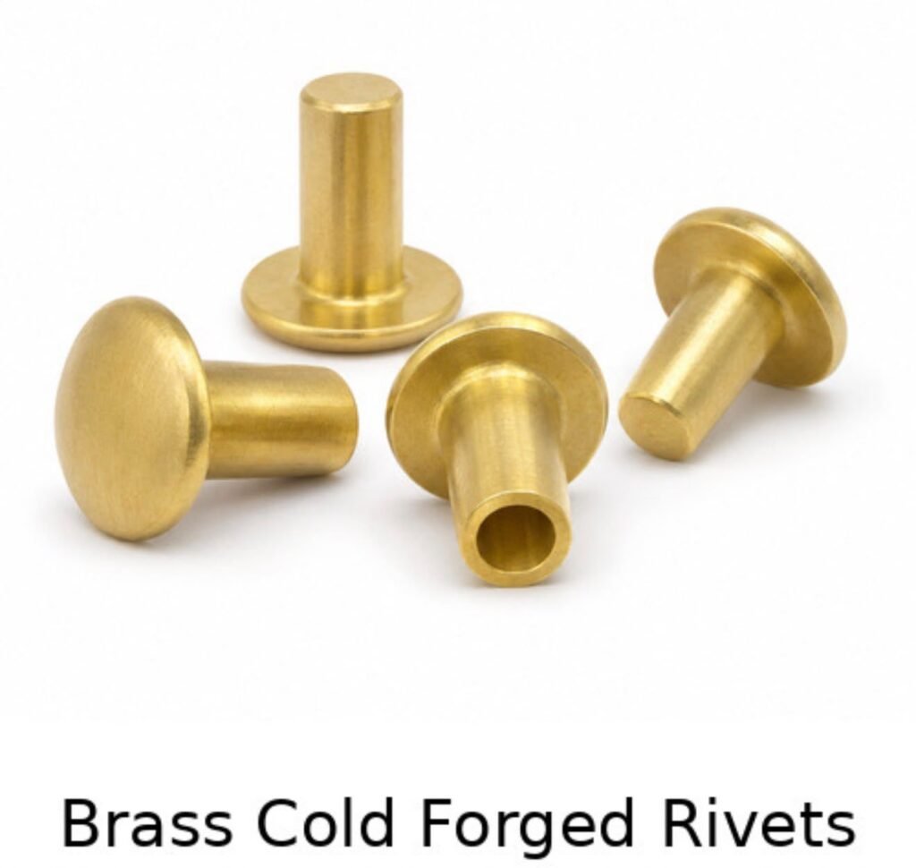
Brass cold forged rivets are permanent fasteners formed by cold heading a brass blank and set by deforming the tail against a prepared assembly. Cable Glands India reviews solid and semi-tubular rivet designs for electrical OEMs, EPC contractors, utilities and distributors. Buyers can define the factory head, shank, tail and coating against the actual material stack, setting tool and functional test. The supplied rivet and the installed joint each need their own acceptance dimensions.
Price: US$ 16/kg
Detailed product overview
Solid brass rivets
A solid tail can be upset into a shop head with the correct tooling and access. Specify protrusion for the full stack range and confirm space for the setting anvil. Tail deformation changes shank fit and head shape. Setting samples on the actual sheet or terminal helps determine the permissible flare and installed height. Distinguish the supplied length from the length of the joint before setting.
Semi-tubular rivets
A partially hollow tail allows the setting tool to flare the end. The hole depth, ID, wall and concentricity affect how the tail opens. Section samples when visual inspection cannot reveal a split or folded wall. For pivot hardware define end float after setting. A change in anvil nose shape can change the flare even with the same part dimensions.
Round and flat head rivets
Choose the head profile around the permitted outside projection, bearing area and tool access. Round or dome heads offer a raised envelope, while a flat bearing face is useful where the application calls for uniform contact. Head support tooling should match the actual profile. Measure diameter and height independently. A head can pass a height check while a damaged bearing edge still affects seating.
Countersunk brass rivets
A countersunk head can seat flush where the mating component provides the correct angle and depth. Check flushness over the permissible sheet thickness range. In thin material a deep countersink can leave little bearing support. Confirm the rivet angle, mating angle and finished contact condition as part of the joint review. Allow for coatings when flushness is critical.
Shoulder and step rivets
A shoulder can control stand-off or support a pivot. Define shoulder length from a functional datum and state which surface carries the load. If the joined components must rotate, identify required end float and allowable friction after setting. Some step ratios or grooves require a subsequent operation. Check radial clearance and roundness where the shoulder acts as a bearing.
Contact mounting and specialty rivets
Rivets can secure terminal tabs or small subassemblies where a drawing defines the current path and material. Electrical contact rivets with specified contact faces or bonded contact materials need a separate design review. Identify the surface that must stay clean after finishing and setting. Hollow eyelets and blind assemblies require a separate route assessment based on the actual design.
Key features
- Round, flat, countersunk or drawing-specific heads; solid or semi-tubular body.
- Diameter, depth, wall and concentricity on applicable drawings.
- Stack range, mating hole limits, protrusion, anvil profile and installation controls.
- Supplied dimensions plus agreed installed flare, head height and functional tests.
- Drawing-based material, finish and dimensional review before tooling.
Related engineering terms and design details
Factory head and shop head
State head profile as supplied and installed tail shape separately. Use drawing callouts for installed head OD, height, symmetry or allowed cracks where applicable. Specify anvil support for the factory head. Some installations call for an orbital or radial setting motion. Review which characteristics can be verified without destructive sectioning.
Tail cavity and wall thickness
For semi-tubular rivets, a hole diameter on its own leaves important details open. The wall is set by cavity diameter, cavity eccentricity and shank OD. Include hole depth and any bottom radius when they affect the final flare. Provide a section view of the expected installed tail to support the tool trial.
Hole clearance and stack thickness
Record the nominal, minimum and maximum stack and the hole range through each component. Holes that are out of line can score the shank or prevent seating. Excess clearance can shift the parts before forming. Identify any coatings or insulation in the stack and any positional tolerance that affects access or alignment.
Installed shear and push-out
Define the joint-level test and load direction before quoting a strength requirement. The fastener, substrate, hole clearance and formed tail all contribute to the result. Retain production-intent coupons or complete assemblies for trials. Specify whether failure is defined by first movement, visible damage or complete separation.
Plated brass rivets
Agree the coating specification and the areas subject to measurement. If the coating follows the upset tail, inspect after setting for the condition specified by the application. Consider coating effects on fit and contact. Electrical checks should use the actual installed stack and an agreed measurement method.
Rivet feeding and setting access
Provide feed orientation and available access to both ends where applicable. Distinguish ram force from the force or stroke control method on the production machine. Set up a process window using installed dimensions and the agreed function test. Define packaging around feeding reliability and part protection.
Technical specifications
| Characteristic | Specification basis |
|---|---|
| Head and shank | Round, flat, countersunk or drawing-specific heads; solid or semi-tubular body. |
| Tail cavity | Diameter, depth, wall and concentricity on applicable drawings. |
| Setting inputs | Stack range, mating hole limits, protrusion, anvil profile and installation controls. |
| Acceptance | Supplied dimensions plus agreed installed flare, head height and functional tests. |
| Thread options | Solid and semi-tubular rivets have plain shanks. For special threaded variants, specify UNC, UNS, UNF, BSW or ISO metric on the drawing. |
| Size range | Nominal shank diameter: 1/8″–2″ (inch range) or 3–50 mm (metric range), depending on design. |
| Dimensional tolerances | Drawing-controlled. Identify finished dimensions and functional datums. |
| Finish | Bare or a drawing-specified coating, subject to application and process review. |
| Ordering units | Price listed in USD per kilogram. Provide delivery quantity by mass or piece count and agree the unit on the quotation. |
Brass grades and international equivalents
| UNS reference | EN or common designation | Alloy family | Procurement note |
|---|---|---|---|
| UNS C26000 | CuZn30 / CW505L | Cartridge brass | Candidate for demanding forming, especially where substantial upset or tail deformation is expected. Verify the feedstock temper and formability with the producing mill. |
| UNS C26800 | CuZn33 / CW506L (comparison) | Yellow brass | Candidate where the selected wire or rod grade and temper fit the geometry. Check both specifications before allowing substitution. |
| UNS C27000 | CuZn36 / CW507L (comparison) | Yellow brass | Compare against the approved chemistry, incoming form and test requirements before any substitution. Qualify fit, finish and forming behavior with samples. |
| UNS C36000 | Free-cutting brass | Machining comparison | Use for route comparison when machining dominates. Evaluate an alternate grade or process if the cold deformation required by the drawing is substantial. |
| UNS C69300 | CuZn21Si3P / CW724R | Silicon brass | Lead-free specification candidate subject to approved chemistry and application requirements. Evaluate the actual forming route and feedstock before committing to a cold forged design. |
Use these designations as cross-reference guidance. National standards may specify different compositional limits, allowable product forms, delivery conditions and mechanical properties. The approved material specification and lot documentation govern acceptance. Review the alloy and temper for the cold work required by the drawing.
Product types and variants
| Family | Typical scope | Design review |
|---|---|---|
| Solid brass rivets | A solid tail can be upset into a shop head with the correct tooling and access. | Check drawing, fit surfaces and the relevant assembly test before first article approval. |
| Semi-tubular rivets | A partially hollow tail allows the setting tool to flare the end. | Check drawing, fit surfaces and the relevant assembly test before first article approval. |
| Round and flat head rivets | Choose the head profile around the permitted outside projection, bearing area and tool access. | Check drawing, fit surfaces and the relevant assembly test before first article approval. |
| Countersunk brass rivets | A countersunk head can seat flush where the mating component provides the correct angle and depth. | Check drawing, fit surfaces and the relevant assembly test before first article approval. |
| Shoulder and step rivets | A shoulder can control stand-off or support a pivot. | Check drawing, fit surfaces and the relevant assembly test before first article approval. |
| Contact mounting and specialty rivets | Rivets can secure terminal tabs or small subassemblies where a drawing defines the current path and material. | Check drawing, fit surfaces and the relevant assembly test before first article approval. |
Industrial applications
| Application | Typical procurement requirement |
|---|---|
| Switchgear and panel devices | Terminal tab, support and hardware joints with validated access and joint design. |
| Electrical equipment assemblies | Small hinge, pivot, contact mounting or component retention positions per drawing. |
| Distributors and service teams | Revision-controlled rivets with documented grip, head style and finish for specified assemblies. |
Manufacturing process
How to specify the part on a drawing
Start with an installed assembly view and a separate detail of the loose fastener. The assembly view identifies mating components, access for tools, neighboring parts and the required service position. The detail establishes dimensions that can be measured on incoming material. Use a section view when an internal surface, depth or transition controls fit. Give each critical dimension a datum and state whether the limit applies before or after finishing. The same dimension should have a single controlling callout. A purchase order should identify the released drawing revision and any governing specification so two suppliers can interpret the part consistently.
Feasibility of the cold forming route
The sequence starts by deciding how much metal needs to move at each die station. The finished shape is considered together with the feedstock diameter, material condition, lubricant, tool access and method of ejecting the blank. A large change in section may need multiple forming operations. Metal must be able to flow into the head or flange without producing folds at the transition. Sharp corners, narrow webs and asymmetric masses can require radius changes or a secondary operation. Where a radius is part of the application, the drawing should show which mating geometry provides clearance so it can be reviewed before tools are made.
Incoming material and lot identity
Define the alloy by designation and a material specification suitable for the incoming wire or rod. Temper, dimensions and surface condition can be as important to heading as chemical composition. Receive material with the lot identity and documentation agreed in the order. Where chemistry verification is required, specify the method and limits on the inspection plan. Verify lead and other restricted substances against the applicable customer requirement and the actual grade. Keep the incoming lot connected to the production and finishing batches so a process change or returned part can be traced. An equivalence table helps with purchasing discussions but the approved drawing and certificate govern acceptance.
Cutoff, blank development and forming
A cutoff establishes the volume available to fill the finished geometry. Consistent cutoff mass, straight feed and a sound end condition support repeatable formation. The first station can prepare a blank for a controlled upset. Later stations develop the profile, size an important diameter or create an internal recess where applicable. The tooling sequence and checks depend on the product. Trial blanks should be inspected at intermediate operations so a defect can be traced to the stage that created it. Record the approved first pieces before production and recheck the relevant characteristics after tool adjustment or replacement.
Secondary operations and cleaning
Secondary machining can establish a dimension that requires a tighter tolerance, a controlled finish or a feature that is difficult to form with an axial tool. Call out whether each functional feature may be machined or must remain as formed. Burrs at holes, grooves and transitions can interfere with plating or assembly. State the allowed edge condition rather than assuming a general deburr note gives the desired result. Use a cleaning process compatible with the finish and the end application. Check hidden recesses when they can retain lubricant, chips or debris. A finished part should be measured after the operations that can affect its fit.
Coating specification and inspection
A finish callout should identify the coating, significant surfaces, required thickness, any undercoat and the method used to verify it. The agreed acceptance condition should also address color or cosmetic appearance when the part remains visible. Internal features, recessed faces and narrow pockets can be difficult to measure. Select reference surfaces or an appropriate test section before the order is released. Specify the dimensions that must be checked after finishing and the relevant gauge condition. Use finished parts for assembly tests because friction, clearance and electrical behavior can differ from the bare part. If a coating requires masking, show the boundary on the drawing.
Quality standards, certifications and inspection
| Requirement | What to specify |
|---|---|
| Quality management | ISO 9001:2015 quality management system. Where a certificate is required, request its current edition, applicable scope and manufacturing site. |
| Dimensional references | ASME B18.7 is a reference for selected small rivet and semi-tubular styles where the requested geometry falls within its scope. Establish separately how the finished joint is set and assessed. Compare supplied dimensions with the installed condition using a section when the tail cavity and flare are significant. A round-head solid rivet and a semi-tubular rivet can share a nominal shank diameter while requiring different installed protrusion and different setting tooling. Identify the side that remains accessible during assembly. Set any requirement for head markings or cosmetic appearance on the side the user will see. |
| Rivet inspection | Agree supplied and set rivet acceptance independently. A loose rivet inspection cannot establish the dimensions of the installed head. |
| Material report | Request traceable alloy and temper documentation. Specify the incoming product form and the required report format at enquiry. |
| Regulatory declarations | Provide the applicable RoHS or REACH documentation requirements and any restricted-substance criteria. The declaration depends on the part, grade and application. |
| Approval records | Agree first article measurements, functional test reports, control plan or PPAP submission requirements before production. |
First article approval
Set the first article scope before tooling starts. A report can map measured values to numbered drawing callouts and identify the actual alloy, finish and sample lot. Use an inspection fixture that matches the drawing datums. Separate variable measurements, such as a measured height, from attribute checks, such as acceptance by a functional gauge. Confirm who approves the first article and which changes trigger resubmission. Where the result depends on a mating part, supply representative hardware or a controlled test fixture. Samples used for functional approval should identify their process route so prototype results are interpreted in context.
Production control and sampling
A control plan can identify where each characteristic is checked, how it is measured and what action follows a failed sample. High-risk characteristics may call for different checks from general dimensional features. If the purchase requires a particular sampling procedure, specify the inspection level and acceptance criteria alongside the test frequency. For automatic sorting, define the detectable defects and set up representative limit samples where appropriate. After a stoppage or tool change, identify the first-off verification needed before continuing. Keep the inspection lot linked to the accepted shipment and isolate suspect material while measurements are reviewed.
Measurement and calibration
Choose a measurement method that can resolve the drawing tolerance and reach the actual feature. Use an optical system, fixture, thread gauge or dimensional instrument according to the inspection plan. A measurement at the edge of a radius can vary with fixturing even when the part is stable, so define the measurement location. If the buyer will perform a different incoming method, compare results on the same samples before routine supply. Identify gauge size, tolerance class and condition where relevant. For disputed results, retain samples with lot records and use an agreed reference method.
Assembly validation and use limits
An assembly can fail through the receiving component, coating, fit or installation method even when every loose fastener dimension passes. Use the production-intent mating materials and the intended tools for validation. Define maximum and minimum assembly conditions where variation affects the outcome. Record the loading direction, tightening or setting sequence, and how failure is judged. For electrical equipment, distinguish a dimensional check from qualification of the equipment or verification of continuity through a finished joint. Where vibration, heat, moisture or chemicals affect performance, identify the applicable tests and acceptance criteria with the equipment designer.
Packing and incoming inspection
The packaging method should protect formed heads, edges and coating and should preserve the identity of each lot. Identify part number, revision, quantity, finish and lot information on the package where required. A buyer feeding components automatically may need an agreed cleanliness level or packing arrangement. Small mixed variations can look alike, so separate revisions, sizes and finishes in order lines and containers. Retain enough samples to compare a delivered lot with its approval data if a fit issue arises. Define the receiving inspection that will be used for subsequent deliveries and record any deviations through a controlled approval.
Engineering changes and repeat supply
When a drawing or finish changes, review the effect on dies, gauges, fixtures, sample approval and inventory. Changes in mating hardware can also affect fit even when the fastener drawing stays the same. Identify which revision a given order must receive and whether the new part is interchangeable with current stock. Avoid mixing revisions in the same container unless the customer has agreed to it. On repeat orders send the released documents and reference the approved sample or inspection plan. Flag any change in annual demand, application, packaging or test method when requesting updated pricing.
Why choose Cable Glands India
Cable Glands India reviews drawing-defined fasteners in Jamnagar, Gujarat, India. Request production samples and an agreed inspection plan. Enquiries are welcome from India, the United States, the United Kingdom and other export markets.
Establish the purchase baseline
Include a part number, drawing revision, exact alloy and finish code, annual requirement and anticipated release quantity in the RFQ. Flag a mandatory manufacturing route, such as an as-formed bearing seat, when it is a design requirement. State the units for dimensions and distinguish shop tolerances from functional limits. If the part replaces hardware in an installed assembly, attach the approved earlier drawing or confirm which interfaces must match it. A quantity estimate is useful for tooling review, and lot size helps determine a sensible inspection and delivery plan. Keep samples identified by revision when multiple alternatives are submitted.
Separate dimensional and functional approval
Use dimensional inspection to confirm the component detail. Use an approved assembly fixture or representative mating parts to verify the performance expected in service. Put the numeric criterion, test method and acceptance condition on the purchase documents. Test reports should identify whether samples are bare or finished and whether fixtures reproduce the receiving part. If production tooling is required to reproduce a feature or material condition, qualify parts from the actual tool sequence. Confirm whether any tested or sectioned specimens are retained for records or excluded from the delivery quantity.
Confirm supply scope with the quote
The listed rate gives purchasing teams a common reference in USD per kilogram. A formal quotation identifies the drawing, alloy, finish, inspection scope, volume and any tooling or sample charges. State the destination and packing requirement to align the quote with the delivery program. If parts are supplied in piece counts, agree on the pricing and shipment units to avoid conversion differences. Identify any documentation that must travel with each lot. Cable Glands India can review the part and related fasteners as one enquiry while keeping each drawing revision and acceptance requirement separate.
Frequently asked questions
Are these blind rivets?
The core range covers drawing-based cold headed solid and semi-tubular rivets. Send the body and mandrel design separately for any blind system review.
What sets the required rivet length?
Use the full stack range plus the protrusion needed to create the approved installed head.
Why does a semi-tubular tail split?
Material condition, eccentric wall, excessive flare, tool geometry and alignment can contribute. Check a section of the installed joint.
Can a rivet remain free to rotate?
A shoulder design can be reviewed against the required pivot clearance, installed end float and friction.
Can I specify a flush head?
Define the permitted flushness and match the rivet head and mating countersink over their tolerance ranges.
Do you offer an electrical rating per rivet?
An electrical requirement belongs to the approved assembly. Supply the specified test method and joint details.
How should shear or pull-out be verified?
Specify the substrate, fixture, load direction and failure criterion using representative installed joints.
What sample helps validate the tail?
Provide actual stack coupons and the production setting tool or the relevant anvil geometry and operating settings.
What is the listed price?
The listed rate is US$ 16/kg. Send the drawing, intended setting method and order volume for a quote.
Equivalent product and related terms
| Language | Trade terms |
|---|---|
| Spanish | Remaches de latón forjados en frío, remaches macizos, remaches semitubulares |
| Russian | Латунные заклёпки холодной высадки, сплошные заклёпки, полупустотелые заклёпки |
| French | Rivets en laiton forgés à froid, rivets pleins, rivets semi-tubulaires |
| Portuguese | Rebites de latão forjados a frio, rebites maciços, rebites semitubulares |
| Italian | Rivetti in ottone stampati a freddo, rivetti pieni, rivetti semitubolari |
Related brass fasteners and parts
- Brass Cold Forged Parts and Cold Forged Components
- Brass Cold Forged Nuts
- Brass Cold Forged Screws
- Brass Cold Forged Bolts
- Special Brass Cold Forged Fasteners
- Round Head Rivets
Request a quotation
Send your drawing, alloy, finish, order volume and delivery destination. Include mating parts, inspection requirements and approval schedule.