Bell Entry Copper Cable Lugs
Rate: US$ 17.90/Kg
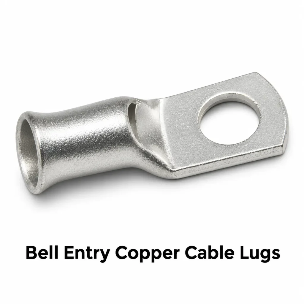
Bell entry copper cable lugs are tubular compression terminals with a flared barrel mouth that guides the stripped conductor into the bore. A bolted palm connects the crimped cable to a stud or busbar. The bell mouth is especially useful during assembly of stranded copper conductors.
US$ 17.90/Kg
Barrel design and inspection vent
The entry flare guides insertion. The straight section of the barrel forms the crimp zone. A vent on selected configurations allows visual inspection of conductor insertion. The lug drawing identifies the bore, usable insertion depth and palm dimensions.
Metric size and dimensional reference
Selected dimensions from the BEWL bell-mouth catalogue. Cable Glands India availability and supplied dimensions follow the approved product drawing.
| Conductor (mm²) | Nominal metric stud | Overall length J (mm) |
|---|---|---|
| 1.5 | M3, M4, M5, M6 | 18–21 |
| 2.5 | M3, M4, M5, M6, M8 | 19–26 |
| 4 | M4, M5, M6, M8 | 21–28 |
| 6 | M5, M6, M8, M10, M12 | 22–34 |
| 10 | M5, M6, M8, M10, M12 | 23–37 |
| 16 | M5, M6, M8, M10, M12 | 25–40 |
| 25 | M5, M6, M8, M10, M12 | 30–41 |
| 35 | M5, M6, M8, M10, M12, M14 | 36–47 |
| 95 | M8, M10, M12, M14, M16, M20 | 52–66 |
| 120 | M8, M10, M12, M14, M16, M20 | 55–68 |
| 150 | M8, M10, M12, M14, M16, M20 | 64–72 |
| 185 | M10, M12, M14, M16, M20 | 67–75 |
| 240 | M10, M12, M14, M16, M20 | 76–82 |
| 300 | M10, M12, M14, M16, M20 | 95 |
| 400 | M12, M14, M16, M20 | 102 |
| 500 | M14, M16, M20 | 112 |
American conductor sizes
American conductor sizes use AWG or kcmil. Typical enquiry designations include 16, 14, 12, 10, 8, 6, 4 and 2 AWG, 1/0 through 4/0 AWG, and 250 through 800 kcmil. These are enquiry designations. The qualified barrel and tooling combination governs compatibility.
Applications and finish
Bell entry lugs are used for bolted copper cable connections in distribution panels, machinery and switchgear. The reference family is made from electrolytic copper with a tin-plated finish. Actual material, coating and inspection requirements follow the ordered configuration.
Manufacturing and quality checks
Typical production forms the barrel entrance and mounting palm from a copper tube blank, then produces the stud hole, deburrs the edges and applies the specified finish. Dimensional inspection can cover the entry flare, barrel bore, insertion depth and palm geometry. Connection qualification applies to the complete conductor, lug and crimp-tool combination.
Flared entry, crimp zone and inspection vent
The flared mouth guides a stripped bundle into the straight bore and helps keep the outer strands together during insertion. The straight barrel provides the compression zone. An inspection vent on a vented design allows visual confirmation of insertion. It cannot establish the quality of the completed crimp. Barrel bore, insertion depth, cable strip length and the approved die sequence depend on the selected combination. The insulation outside diameter is a separate dimension used when sizing a boot or heat-shrink sleeve.
How the barrel and palm work together
A tubular cable lug brings together two interfaces with different mechanical requirements. Inside the barrel, the conductor strands occupy a defined bore and are compressed by the approved die. At the palm, the lug bears against an equipment contact surface under the specified bolted assembly. The design has to accommodate both interfaces within the space available in the enclosure. A suitable conductor fit therefore addresses only one part of the selection.
The transition between the barrel and palm also affects the installed shape. Its position determines how closely the cable can approach the mounting face and how much room remains around the fastener. A smooth dimensional transition helps the component fit the intended assembly, but photographs seldom show all of the critical clearances. A side view and a plan view together show the relationship between the mounting hole, barrel axis and available contact area.
For repeat purchasing, the complete configuration is more useful than a description such as copper lug or heavy-duty lug. Conductor size, cable construction, mounting hole, barrel length, palm geometry and finish define a reproducible component. This combination allows the purchasing team to compare quotations against the same intended termination.
Cable construction and barrel selection
The conductor within a power cable can be assembled in several ways. Two cables carrying the same nominal cross-section may have different strand counts and different bare bundle diameters. Compaction can change the outer shape of the bundle, while fine stranding changes how the bundle behaves during preparation and insertion. The applicable lug and tooling instructions identify the conductor constructions supported by a particular termination.
Barrel bore is consequently a functional dimension. The cable must enter to the intended depth while remaining within the range covered by the approved crimp process. An oversized barrel does not automatically accommodate a smaller conductor satisfactorily, and a conductor that physically enters a barrel does not automatically qualify the connection. The relationship between the conductor, barrel wall and die geometry determines the finished compression.
For a manufactured cable assembly, the cable part number is useful alongside its nominal size. It connects the lug selection to a specific conductor construction and insulation system. That information also helps control future substitutions. If a purchasing change introduces a different cable, the existing lug and tooling combination can be reviewed against the revised construction before the assembly is released for production.
Understanding dimensional information
A dimensional table should identify what each measurement represents. Overall length describes the complete lug from the palm end to the barrel entrance. Barrel length describes a different portion of the component, and usable insertion depth may differ again where an internal feature limits conductor travel. Treating these values as interchangeable can lead to an incorrect strip length or an unexpected cable exit position.
Palm width is measured across the flattened terminal portion. Palm thickness affects the fastener stack, while the hole centre position determines where the lug sits on the equipment stud. The distance from the hole to the barrel shoulder matters when the mounting pad is narrow or the tightening tool needs to approach close to the barrel. A drawing can show these relationships more clearly than a single product photograph.
Dimensional units also belong with the values. Metric conductor area is expressed in square millimetres, while lug dimensions are commonly expressed in millimetres. AWG and kcmil describe American conductor sizes. Inch dimensions may describe an American mounting fastener. Keeping these units explicit allows the component to be compared with the cable and equipment documentation without assuming that every number represents the same kind of measurement.
Contact surfaces and fastening arrangement
The palm forms the bolted contact surface at the equipment terminal. Its usable footprint depends on the shape and dimensions of the mating pad. A wide palm can still have limited support if it extends beyond the pad, and a barrel shoulder can prevent full seating if it interferes with an adjacent feature. The equipment assembly drawing establishes the intended position of the lug and the associated hardware.
The fastening arrangement includes the bolt or stud, washer arrangement and any specified locking components. These items contribute to the complete joint. Their selection and tightening requirements come from the equipment or connection specification. A general catalogue page cannot establish one torque value for every stud size, fastener material and terminal construction.
Cable routing influences this interface as well. A cable that is forced sideways after the palm has been attached can apply a load to the terminal. Suitable support and a planned cable path allow the lug to sit in its intended position. This is particularly relevant for large conductors, which can occupy substantial space and resist being moved into a tight bend near the barrel mouth.
Applications in machinery and control equipment
Industrial machinery often uses bolted power connections in a limited enclosure space. Straight single-hole tubular lugs provide a defined cable entry direction and one mounting point. Their suitability depends on the terminal layout, conductor construction and qualified connection system. The cable path may pass through ducts, supports or protective sleeves before reaching the termination.
Control equipment can contain terminals of several different sizes within the same assembly. The lug palm and fastening tool need enough space around each connection, and the cable arrangement must respect the equipment layout. A compact lug can simplify the mechanical arrangement where its conductor capacity and tooling are suitable. The available space for a protective cover can be as important as the bare lug envelope.
Production cable assemblies also benefit from consistent identification. A drawing or bill of materials can connect the cable length, lug configuration, orientation and protective sleeve to one assembly revision. When several similar lugs are used in the same panel, that identification helps distinguish a change in stud size from a change in conductor size. Both differences may be difficult to recognise from a packed component alone.
Application planning for large conductors
Large power conductors introduce handling considerations beyond the dimensions of the bare lug. The cable bend radius, cable weight and location of the first support influence how the completed termination fits. An overall length that appears suitable on a component drawing may leave too little room once the insulated cable and its protective covering are included.
A straight lug establishes the direction of the cable immediately beyond the barrel. Where the enclosure requires the cable to turn, the bend begins outside the termination according to the cable assembly requirements. The available routing space can therefore influence whether a straight or angled product is appropriate. The related angled lug pages describe alternative geometries for that equipment layout decision.
Tooling space is another consideration for larger barrels. The crimp head and dies can require more room than the finished lug occupies. Assembly planning includes the sequence in which the conductor is inserted, the crimp is completed, the protective sleeve is positioned and the palm is secured. An accessible finished connection does not necessarily provide access for every earlier manufacturing operation.
Material, finish and document identification
The copper grade and finish form part of the ordered component specification. A grade designation identifies the material requirements associated with the approved drawing. A finish description identifies the surface treatment, while the agreed inspection criteria define how that finish is assessed. These characteristics can be recorded separately so that a coating change is distinguishable from a change in the underlying material.
Material documentation, dimensional inspection and finish records each address a different aspect of the supplied part. Their usefulness depends on their connection to the ordered configuration and production batch. A report describing another size or a different finish does not establish the characteristics of the delivered component. The purchase documentation can identify which records accompany the order.
Product qualification adds another layer of information because it concerns the complete connection under defined test conditions. The lug, conductor and installation tooling must be identified within that evidence. Product descriptions can refer to standards where applicable, while claims of certification require the relevant supporting documentation for the actual supplied product. This distinction helps buyers understand the scope of the records associated with their order.
Variants within a bell entry lug family
Several variants can share a single-hole layout while serving different assembly requirements. Barrel length, palm width, mounting hole and finish can change independently within the limits of the design. The word tubular describes the barrel construction, and the single-hole designation describes the mounting arrangement. Neither term by itself gives every dimension needed to identify the part.
A family table is most useful when it connects each configuration to a clear drawing or part reference. That reference allows the same item to be reordered even when other similar products are listed nearby. It also helps avoid assuming that all stud sizes are available for every conductor cross-section. The combinations offered for an order depend on the available design and its qualification.
For buyers comparing straight, two-hole and angled products, the starting point is the mating equipment. The mounting pattern and cable approach establish the geometry. The conductor and installation requirements then establish the barrel and tooling combination. The related product links provide a way to compare these different lug forms within the Copper Cable Lugs range.
Barrel length and bell-entry cable routing
Barrel length affects the space occupied by the completed cable termination. A short barrel can suit a compact panel where the distance between the busbar and the cable support is limited. A long barrel provides additional axial length for the crimp pattern associated with that design. The number and location of crimps follow the qualified tooling instructions for the individual lug. Barrel length alone does not establish the current rating of the connection.
The cable also needs room beyond the barrel mouth. This space accommodates the cable bend radius, insulation sleeve and first mechanical support. A termination can fit on the mounting stud while leaving insufficient room for the cable to approach without side load. Overall length, barrel length and cable exit position therefore belong together in an equipment layout review.
Bell-entry palm geometry and stud clearance
A single-hole palm provides one bolted attachment point. Its geometry includes the clearance hole, palm width, palm thickness and distance from the hole centre to the barrel transition. These dimensions affect washer seating, contact area and access for tightening tools. The palm should seat on the intended equipment contact face without interference from the barrel shoulder or adjacent insulating parts.
The nominal stud designation refers to the fastener. The clearance hole is a separate dimension, allowing the lug to pass over that fastener. A metric M8 stud and an 8 mm clearance hole are different specifications. American fasteners likewise use nominal inch dimensions, with the actual clearance governed by the approved drawing. Conductor cross-section and mounting hole size remain independent selection parameters.
Metric, AWG and kcmil conductor designations
Metric conductors are commonly described by nominal cross-sectional area in square millimetres. American conductors use AWG and, for larger sizes, kcmil. These designations help identify the cable, but a nearby numerical conversion does not establish that the same lug accepts both conductors. The barrel and crimp tooling must be compatible with the conductor construction being terminated.
The strand count, individual strand diameter and compaction affect the shape and diameter of the bare bundle. Flexible and compacted conductors can behave differently during insertion and compression. A useful product specification therefore identifies both the nominal size and the supported cable construction. The nominal sizes listed on this page are enquiry designations, with the supplied combination governed by its drawing and installation instructions.
Bare copper and tin-plated finishes
Bare copper and tin-plated copper are finish options that serve different purchasing specifications. The ordered finish applies to defined surfaces and has its own inspection criteria. On a tin-plated lug, coating thickness and coverage are distinct characteristics. A visually bright surface alone does not establish coating thickness or acceptance against an agreed finish specification.
The mating terminal surface is part of the joint design. Plating on the lug does not by itself establish suitability for every conductor material, enclosure environment or equipment terminal. Material compatibility and the complete connection specification govern the application. Packaging and handling also matter because damage or contamination on the palm can affect the condition of the contact surface before assembly.
Panel, switchgear and busbar applications
In distribution panels, a straight tubular lug joins a cable to a bolted terminal while allowing the conductor to approach along the barrel axis. The space occupied by the palm and tightening tool must fit within the terminal compartment. Cable management determines the position of the first support and the path of the insulated cable away from the connection.
Switchgear and industrial busbar assemblies can use several lugs close together. Palm width, insulation clearance and cable routing then become interdependent. The application drawing establishes phase spacing and any protective barriers. Where cables run vertically, the support arrangement carries their weight so that the lug and stud connection are not used as the sole cable support.
Crimp barrel, insertion depth and tool access
The barrel has to accommodate the stripped conductor to the intended insertion depth. The cable preparation length follows the lug and cable assembly instructions. A strand bundle that enters only part of the required depth changes the conductor engagement within the compression zone. Inspection of preparation and insertion is therefore an assembly control before the crimp operation.
Tool access deserves its own layout check. A die set occupies space around the barrel, and a powered crimping head may need room to approach from a particular direction. Some assemblies are crimped before the palm is bolted to the equipment. Others allow crimping in position. The assembly sequence depends on the equipment layout, cable handling requirements and approved tool.
Dimensional inspection and production records
Dimensional inspection can cover the barrel bore, outside diameter, usable insertion depth, overall length, palm width and mounting hole position. The approved drawing defines the dimensions and tolerances that determine acceptance. Material records and finish inspection provide additional information about the ordered component.
Electrical and mechanical qualification concerns the assembled termination. Its result depends on the lug, conductor and tooling combination as well as the test method. A dimensional inspection report establishes conformity with the inspected drawing characteristics. Qualification records address the performance conditions covered by the particular test. The quotation identifies the documentation agreed for the supplied order.
Bell-mouth entrance and strand guidance
The bell entry is the flared opening at the cable end of the lug. Its wider entrance helps guide the prepared conductor bundle toward the straight barrel bore. This feature is useful to describe separately from the barrel bore because the entrance diameter and the compression portion have different functions. A large entrance does not establish the conductor capacity of the complete barrel.
During preparation, the stripped strand bundle must retain the construction required by the cable assembly instructions. The flare guides that bundle into the selected barrel. The applicable insertion depth and crimp pattern remain properties of the qualified lug and conductor combination. The bell-mouth feature therefore belongs within the complete product specification alongside conductor size, barrel dimensions and tooling.
A drawing can identify the maximum entrance diameter, flare length and the position where the straight bore begins. These features influence both insertion and the space occupied by the finished terminal. They are also relevant when a sleeve or protective covering surrounds the barrel entrance. The covering has to accommodate the actual external geometry of the ordered part.
Inspection vents and insertion checks
Some bell entry configurations incorporate an inspection vent. The opening provides a view of conductor insertion at the location established by the design. Its position relative to the barrel and palm is part of the component drawing. A vented configuration and a closed configuration can therefore require different inspection arrangements during cable assembly.
The inspection opening addresses one stage of assembly. The completed crimp also depends on conductor preparation, the selected tooling and the approved compression sequence. Visual access through the vent cannot establish every characteristic of the finished electrical connection. The assembly procedure identifies the checks used before and after compression.
Inspection records can distinguish these stages. An insertion check confirms the condition observed before crimping, while a dimensional or process record addresses the completed operation. Where qualification testing is required, its documentation identifies the complete combination and test conditions. This gives the equipment manufacturer a clearer basis for relating assembly checks to product performance evidence.
Bell entry lugs in repetitive cable production
In repetitive cable assembly, a clearly identified component helps operators distinguish conductor sizes and mounting options. Bell entry lugs may share a similar outer appearance while differing in bore or palm geometry. The ordered part reference connects those features to the cable assembly bill of materials. Packaging labels and work instructions can use that same reference throughout production.
The cable preparation operation precedes insertion. The prepared conductor must suit the usable barrel depth, and its insulation remains outside the intended compression zone according to the assembly instructions. The flare is a feature of the lug entrance, while the straight barrel is the location of the approved crimp pattern. Maintaining this distinction helps describe the component without treating the entire length as one uniform bore.
Tool access is considered around the compression portion of the barrel. The crimp head must reach the specified locations while the conductor remains correctly positioned. In a cable assembly shop, this can be planned before the lug is connected to the equipment. In an equipment enclosure, surrounding components may affect the practical assembly sequence.
Metric and American cable identification
The metric chart uses nominal conductor areas in square millimetres and nominal metric stud sizes. American enquiries use AWG or kcmil conductor designations. These systems identify cable sizes through different conventions. A near numerical area conversion does not establish that a particular barrel and die combination accepts both cable constructions.
The conductor data sheet provides the construction information needed alongside the size designation. Strand count, strand diameter and bundle shape influence how the cable occupies the barrel. The bell-mouth entrance helps guide insertion, but the straight bore and qualified crimp process establish the supported combination. This remains relevant when a purchasing team changes cable suppliers.
Mounting hardware is a separate interface. The clearance hole and palm outline must match the equipment connection regardless of the conductor designation used for the barrel. A complete component reference therefore connects the cable requirement and the mounting requirement. The quotation identifies the specific combination covered by the offered product.
Product records and configuration changes
A repeat order can reference an approved drawing and part revision. If the flare, barrel or palm changes, the revision provides a way to distinguish the resulting component from earlier supplies. The effect of the change can then be assessed against the cable preparation, tooling and equipment layout used for the assembly.
Documentation requirements depend on the order. Material records, finish inspection and dimensional reports describe different features of the delivered component. Cable assembly qualification addresses the complete connection. Connecting these records to the part reference and delivery batch makes the information useful during receiving inspection and subsequent production review.
Frequently asked questions
What is a bell entry lug?
It is a compression lug with a flared conductor entry at the open end of the barrel.
What does the flare do?
It guides the stripped copper strand bundle into the barrel bore.
What is the inspection vent for?
The vent provides a visual check of conductor insertion on configurations that include one.
Are metric sizes and AWG interchangeable?
The selected cable construction and bare bundle diameter determine fit. Metric and American sizes are separate ordering designations.
What finish is shown in the reference catalogue?
The reference family uses tin-plated electrolytic copper. The approved product drawing governs the supplied grade and finish.
Does the stud designation give the hole diameter?
The stud designation identifies the nominal fastener. The drawing specifies actual hole clearance.
Which die fits the lug?
The approved installation instructions identify the die and crimp sequence for the selected lug and conductor.
What determines overall length?
The barrel and palm geometry jointly determine the overall length. The length ranges in the chart reflect the listed stud variants.
Request a quote
Contact Cable Glands India for a quotation by cable size, strand construction, mounting geometry and quantity.