Stamped Copper Transformer Connector Tabs and Lead Straps
Rate: US$ 19.50/Kg
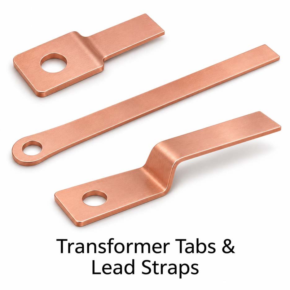 Punched and formed copper sheet and strip components for drawing-specific transformer lead connections.
Cable Glands India supplies stamped copper transformer connector tabs and lead straps for single-phase and three-phase transformer lead assemblies and related power equipment. Request eyelet tabs, straight straps, offset straps and formed connector plates against your drawing, material and finish specification. The sections below describe the interfaces that matter for fit, tooling review and first article approval.
Rate: US$ 19.50/kg
Send your drawing for a quotation · View Copper Stamped Parts
Product designs and application requirements
Eyelet tabs
A pierced tab gives a lead assembly a defined bolted connection point. Show the eyelet position relative to the lead end and identify the bearing surface for the fastener stack.
Show the required finish in the same drawing package as the mechanical features. State whether the drawing dimensions apply before or after finishing. Identify measurement zones separately when an important surface lies inside a bend, around a pierced edge or on a recessed portion of the part. If the finish is specified by a customer standard, include the document and revision. This gives purchasing and quality teams a common basis for quoting, inspecting and releasing the parts, especially when different finishes share the same stamping tool.
Straight lead straps
A flat strap provides a direct route between two lead interfaces. Define the finished width and mating area at both ends, particularly if one end necks down for clearance.
Ask the assembly team which operation sets the part position and which feature must stay clear during installation. A datum should reflect the way the part is seated or held in service wherever practical. Check that the chosen datum is also accessible for measurement. An assembly fit check can catch stack-up across multiple parts, while a dimensional report shows which feature contributes to the stack. Both records help if a future drawing change changes the fit of a component that previously passed incoming inspection.
Offset lead straps
A formed step can route a strap around a support or insulating barrier. Control the finished offset and show the installation direction relative to nearby features.
List the electrical and mechanical tests that will be run on the assembly and identify any sample requirements early. Current, force, temperature or retention targets should be tied to the actual mating hardware and test conditions. The stamping drawing can control geometry, material and surface condition. The assembly test establishes performance under the specified duty. When a customer needs documentation for design approval, agree which evidence comes from raw material records, which comes from stamped part inspection and which will be supplied by the assembly test program.
Formed connector plates
A connector plate may combine a bolted face with a formed leg for the lead. Dimension both interfaces independently and include the relationship between their planes.
Use a section view when important features are hard to read in plan view. Include bend reliefs, edge breaks or local changes in thickness where they affect clearance or strength. If an edge faces insulation, an operator or another critical surface, specify the edge treatment on that side. General deburring notes can be supplemented with explicit zones for special treatment. Agree on an inspection method that distinguishes a measurable burr from a rounded or polished edge, particularly if the part will be inspected after finishing.
Winding-side interface
Show how the lead is joined to the stamped part and provide the mating lead section. Define joining allowances, access and the portion that must remain free of coatings or contamination.
Include the expected ordering pattern when requesting a quotation. A prototype batch, a qualification run and a recurring production order can have different setups and inspection needs. If samples are needed ahead of production, indicate which checks they must support and when the mating components or fixtures will be available. Share likely lot sizes and annual demand so the tooling proposal reflects how the part will be made and replenished. Record separately any dedicated gauges, fixtures or special packaging included in the commercial scope.
Bushing-side interface
Where the strap connects near a bushing, provide the complete hardware stack and lead orientation. Check movement and access during assembly so tightening does not load the surrounding insulation.
State the allowed variation on the finished part and show which dimensions are basic or reference-only. Redundant tolerances can make a drawing harder to inspect and can obscure the dimensions that govern assembly. Where several features must line up together, define their relationship from common references. Review the proposed measurement method during sample approval. If different methods can produce materially different readings, agree which method controls acceptance and record any fixture pressure, support points or alignment steps needed for repeatable results.
Insulation clearance
Identify keep-out zones and nearby insulation surfaces on an assembly drawing. Specify edge treatment where the strap approaches paper, sleeving or another barrier.
Describe the condition in which the part will reach the assembly station. The finish may be accepted on a sample before packaging, while transport and bulk handling can affect its appearance or shape. Define surfaces that require separators, individual cavities or another form of protection. Include pack quantity and label requirements where parts feed directly to production. If the handling method changes between sample and production quantities, check that the production pack still preserves the features that were qualified on the sample.
Lead routing
The strap should fit the intended assembly sequence as well as its final position. A section view can show whether workers can insert, align and secure it without forcing the lead.
Discuss part orientation during tool review. Bend direction, trim direction and the placement of carrier ties can affect which face carries a burr or tooling mark. Review candidate tie locations against critical surfaces and mating zones. Where witness marks are permitted, place them on the drawing or on an approved sample. Where they are restricted, identify the relevant surface and reason, such as sliding fit, insulation clearance or contact area. That detail helps evaluate the tooling proposal and gives inspectors an objective basis for acceptance.
Joint preparation
Document the joining method and preparation expected at each end. Brazed, welded and bolted configurations can have different surface requirements, even on parts with the same outline.
Treat revision control as part of the purchase specification. Use the same drawing number, revision and finish code on the quote, order, sample report and shipment label. Identify similar parts that must be segregated, including mirrored or differently plated versions. If a revision changes geometry or material, state the date or order from which the change applies and whether old stock can be used. A retained sample and a traceable inspection record can help reconcile dimensional differences found during assembly after a revision change.
Oil and dry-type environments
State the transformer environment and any restrictions on residues, finish or packaging. Use the approved assembly specification to decide which materials and finishes are acceptable.
Define approval at the feature level. A visual sample can establish an appearance limit, a dimensional report can document measured geometry, and an assembly trial can establish installation fit. Specify which evidence is required for each critical characteristic. If a dimensional feature is hard to measure without damaging the part, discuss destructive sampling or an agreed proxy during tool planning. Record how production samples will be taken and what action follows an out-of-tolerance result, including any need to segregate affected lots.
Bend orientation
Mark the bend direction on a section view and establish the reference face. With mirrored straps, use separate part identifiers and provide a clear visual cue where feasible.
Identify which dimensions are especially sensitive to material variation or press setup. A part that leaves the tool with an acceptable outline can still show changes in formed height, local twist or contact angle. Agree on a representative sampling plan across a run when those changes affect installation. Where the customer uses a check fixture, share its seating method and reference geometry with the manufacturer. Comparing the two inspection setups during sample approval can prevent disagreement when parts arrive at the assembly plant.
Load and movement
Review how the strap is supported and where it may move in service. The transformer designer should evaluate electrical duty and mechanical loading on the installed assembly.
Specify the surface condition needed at delivery, including any allowed handling residues and the method of protection after finishing. If the part will be joined or plated again downstream, communicate the cleaning and surface preparation requirements for that process. Agree whether appearance is assessed in natural light, under magnification or against a retained sample. The finish requirements should distinguish the surfaces that are visible in the final assembly from those whose surface condition affects electrical, mechanical or joining performance.
Critical interfaces
Use the mating plane and mounting hole or tab edge as functional references. Compare the formed condition to the assembly drawing before releasing production tooling.
Finish the review with a clear list of release inputs. These typically include a current drawing, material and temper, finish specification, expected order quantities and acceptance criteria. Include a model or a sample where it resolves assembly details. For export shipments, identify packing, labeling and requested quality documents up front. This helps the quote reflect the actual scope and gives both purchasing and production teams a single specification to use when moving from prototype approval to repeat supply.
Cleanliness and handling
Specify protected surfaces and cleanliness requirements for the actual joining process. Pack stamped lead straps so edges cannot score either the neighboring components or their contact areas.
Include a dimensioned view of the mating component with the request for quotation. Mark the features that establish fit and the surfaces that actually touch in the finished assembly. This lets the tooling review separate the tolerances needed for fit from those needed for current transfer. It also helps establish whether first articles can be inspected with standard instruments or need a dedicated fixture. Where the customer provides both a model and a drawing, identify which revision controls and call out any dimensions that the model alone cannot communicate.
Engineering changes
Track strap revisions separately when bend angle, lead position or hole location changes. Include mating component revisions so the sample represents the intended build.
Provide nominal geometry and acceptance limits for the finished part. A formed component can measure differently when it is free on a bench and when it is restrained in an assembly. If the mounting condition controls fit, define the restraint and its location in the inspection plan. Review sample parts in the same orientation used during installation. Where the design has handed versions, include a view that makes the handedness unambiguous, since similar parts can be difficult to distinguish during incoming inspection or line-side picking.
First article fit
Use a representative bushing, lead or fixture to check fit and access. Record where the strap seats and whether it needs adjustment before bolting or joining.
Review material and geometry together during die design. Copper grade, temper, thickness and bend direction influence how a formed feature behaves, so the material specification should travel with the dimensional drawing. If multiple grades are acceptable, identify them as approved alternatives and state whether each requires separate approval. A dimensional first article from one material should be traceable to its lot and temper. For repeat orders, retain that information so changes in material condition can be evaluated against the original qualification record.
Specifying the winding, routing and termination zones
Break the drawing into the winding end, the routed strap and the termination end. At the winding end, document the joining process and the clearance needed for joining equipment. Along the strap, show which bends set the route and which edges lie near insulation. At the termination end, give the mounting hole, bearing land and reference face. If the strap must be held during tightening, show where the assembly worker can hold it. For transformer platforms that use similar straps, compare each approved sample with the build configuration it serves and identify the parts clearly on drawings and labels.
Technical specification checklist
| Specification | What to provide | Why it matters |
|---|---|---|
| Part identity | Part number, revision, sample or model | Matches the order, inspection report and packaging |
| Base metal | Copper grade, temper and strip thickness | Connects raw material purchasing with functional requirements |
| Formed geometry | Bend radii, final angles, offsets and handedness | Defines the geometry that mates with the assembly |
| Interface | Contact zones, datums, mating component and functional fit | Provides a basis for the sample fit check |
| Edge and finish | Burr limits, plating, critical surfaces and inspection zones | Shows where surface condition affects use |
| Approval | Inspection method, sample quantity and document requirements | Sets acceptance criteria before production |
| Order and delivery | Lot size, annual usage, packaging and ship-to details | Clarifies the recurring supply scope |
Materials, manufacturing and order requirements
Copper grade and temper
Use the customer drawing to specify the copper grade and temper. C11000 ETP and C10200 oxygen-free copper can be considered when the design calls for high conductivity, subject to review of forming and joining requirements. A spring function may call for a higher-strength copper alloy and a validated working deflection. Material selection starts with the electrical duty, mechanical function, environment and joining process. Supply the exact purchase specification if a particular material certification, strip condition or direction of rolling must be preserved. For a design transferred from another supplier, include the existing material specification and approval history where available.
Strip thickness and bend feasibility
Give the nominal strip thickness and tolerance together with the final formed dimensions. The design should show internal bend radii and any features close to a bend line. Material displaced during forming can influence adjacent holes or slots, and a tight bend may require review of both material and tooling. Distinguish stock thickness from locally formed or coined thickness. For any feature that has to mate with another component, give the acceptable finished thickness at the point of engagement. If the drawing uses a generalized thickness note, identify the zones where a local deviation matters to the assembly.
Bare and plated finishes
Bare copper and tin, nickel or silver finishes can be discussed against the drawing. The request should say where the finish is needed, how thick it must be and whether a test or certificate is required. If the same part number has multiple finishes, identify a separate finish code so the quote and label remain clear. Review post-stamping coverage if cut faces or pierced holes are functional. Review prefinished strip when carrier handling or downstream assembly calls for a specific surface condition. For either route, communicate any restrictions on discoloration, exposed substrate or contact with packaging material.
Progressive or staged tooling
A repeat production job can use a progressive sequence of piercing, blanking, forming and cut-off operations where the geometry and quantities support that route. A staged process can be evaluated for sample lots or designs requiring individual operations. Tooling selection depends on strip utilization, form sequence, handling and inspection access. Before tooling release, identify the sequence most likely to preserve critical features. Discuss tool ownership, maintenance and storage on repeat programs if they are important to the sourcing agreement. Document any changes from the qualification method before the next run is released.
Drawing package and quotation
Send the drawing number and revision, model if available, material grade, temper, finish, sample quantity and annual usage. Include the mating interface if the geometry is controlled by a larger assembly. A quote can then separate the recurring part cost from tooling, inspection or packaging requirements. Identify any approval milestone that needs samples delivered before the production order. Where only a sample exists, use it to establish a review drawing and agree the dimensional and material requirements before release. That gives both the buyer and manufacturer a controlled reference for future replenishment.
First article inspection and production release
Use samples to review both measurable characteristics and actual assembly fit. Identify which dimensions, surfaces and test reports need formal approval. A first article record can carry the part number, material lot, tooling reference, finish and drawing revision so the approval can be traced. If a part is supplied with mating samples, record the revision and setup used for the trial. Production release should follow the agreed approval process. If the drawing changes before production, confirm which features require a new sample and update the order documents to point to the approved revision.
Incoming inspection and traceability
Agree how lots will be identified and how measurement results will be reported. A buyer may need the purchase order, drawing revision, quantity, finish and batch on the shipment label. Quality documentation should reflect the checks required for the part, such as dimensional results, raw material documentation or coating thickness reports. Identify any special sampling rules or record retention period when requesting the quote. If parts will be split into smaller packs downstream, use identification that can be carried into the assembly area. Retaining lot identity helps investigate a fit or finish issue without mixing production batches.
Commercial rate and order scope
The listed rate is US$ 19.50/kg. Request an itemized quotation for the drawing and order quantities so that tooling, sample submission, finish, inspection, packing and delivery terms can be confirmed for the project. Include the expected call-off pattern if the total volume will be ordered in several releases. State the destination and any requirements for labels or supporting documents. For repeat programs, identify the approved part revision and any finish variants on the order. This keeps price discussions tied to the same supply scope and avoids treating differently configured parts as interchangeable.
Frequently asked questions
What transformer connector tabs and lead straps can I request?
The product family covers eyelet tabs, straight straps, offset straps and formed connector plates. These configurations are used in single-phase and three-phase transformer lead assemblies and related power equipment. Supply the specific drawing and application when asking for pricing. Where a part combines several features, identify the critical mounting, mating or joining surfaces so they can be assessed together during the tooling review. A representative sample or assembly view is especially helpful when adjacent hardware controls the final shape.
How much do these stamped copper parts cost?
The listed rate is US$ 19.50/kg. Send quantities, finish and drawing requirements for an itemized quote. The proposal can identify any project-specific tooling, sample inspection, packaging and delivery charges. For repeated releases under a single program, include the expected order schedule so the quote reflects the lot sizes and packing configuration actually required.
Which information should I include with a drawing?
Include the controlled revision, material, temper, finish, critical dimensions and expected production volumes. Where possible, include the mating hardware or an assembly model. An assembly reference helps review installation direction, clearance and orientation. Include the approved inspection method if a feature is checked under restraint or in a dedicated fixture.
Can I request plated copper stampings?
Yes. Discuss bare, tin, nickel or silver finishes with the drawing and service conditions. Specify the surfaces requiring coverage, thickness acceptance limits and how the coating is checked. If exposed cut edges or tooling marks are restricted, identify their limits on a drawing or approved reference sample. Keep finish variants traceable by a separate part or finish code.
Can I order samples before a production release?
Request the sample quantity and approval documentation during quotation. Discuss whether the samples need to come from production tooling and whether they must carry the production finish. A sample review can include dimensional inspection, mating fit and any tests specified for the assembly. Agree how revisions will be documented if a sample leads to a geometry change.
How are tolerances agreed?
The drawing and approved inspection plan establish tolerance limits for each part. Review features such as holes, bends and functional surfaces against the installation condition. Where dimensions depend on support or clamping, agree on the measurement setup. The tolerance review should identify which features require a dedicated gauge and which can be checked with routine instruments.
What documents can I request with the order?
List the documents required for the project, such as a dimensional report, raw material certification, finish inspection or a first article report. Confirm the document format, frequency and traceability information during quotation. If the receiving site uses a specific approval format or labels, share those requirements along with the drawing and purchase specification.
How do I qualify the part for my equipment?
Start with dimensional and material verification, then inspect representative parts installed with the actual mating components. Define the conditions for electrical or mechanical testing, including the applicable loads and environment. Validate the finished assembly against your engineering requirements and record the approved part and drawing revision before releasing recurring orders.
Request a quote for transformer connector tabs and lead straps
Email sales@cableglandsindia.com with your drawing, finish, quantities and required delivery date. Include any sample approval, packaging and inspection requirements. The quotation will define the manufacturing and delivery scope for your part.