Copper Hex Nuts to DIN 934 and ISO 4032
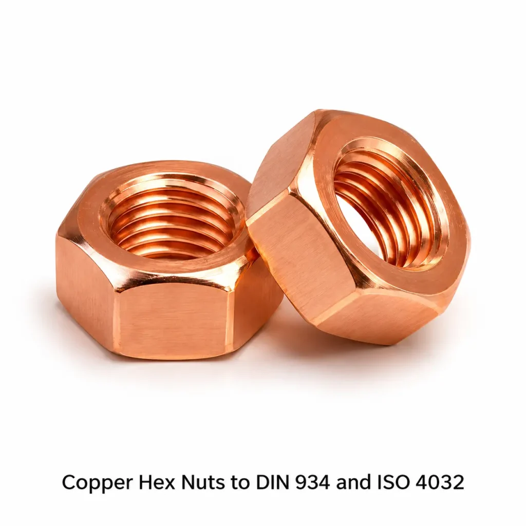
Copper hex nuts with DIN 934 or ISO 4032 dimensional requirements are intended for engineered joints where copper material compatibility, electrical characteristics or an established equipment drawing calls for a copper nut. Cable Glands India offers these components in high-conductivity copper and selected machinable copper grades. Copper requires particular attention to thread engagement, hardness, bearing pressure and tightening practice. A nut having the outline of a standard steel nut does not acquire the same load capacity. The complete connection, including stud, contact surfaces and thermal cycling, must be evaluated for the intended service.
Reference price: US$ 19.00 per kg. Request a firm quotation for the selected alloy, size, finish and order quantity.
Request a quotation from Cable Glands India
Standards, scope and ordering designation
Specify DIN 934 dimensions or ISO 4032 dimensions and the required edition, then separately specify copper grade, condition and acceptance tests. The dimensional reference does not establish copper proof load or justify a steel property-class marking. Metric coarse and metric fine threads must be distinguished. Requested sizes outside the selected dimensional scope are manufactured to the approved drawing. Copper nuts for electrical assemblies are not assigned a current rating solely from thread size, copper percentage or external dimensions. Compliance statements must identify exactly which requirements are satisfied.
Copper alloys and material selection
C11000 electrolytic tough pitch copper is a common high-conductivity choice for electrical components. C10100 oxygen-free electronic copper and C10200 oxygen-free copper may be requested where oxygen control or the equipment specification requires them. C14500 tellurium copper offers improved machinability compared with many high-purity copper grades, but its composition and properties must be accepted by the designer. CW004A, CW008A and CW118C appear in European copper specifications for relevant material families; full specification comparison is needed before approving any cross-reference. Hardness and temper materially affect how a copper nut responds to tightening. Soft copper may deform at its bearing face or threads, while harder conditions can change forming and machining behaviour. Conductivity, chemistry, strength and dimensional stability must therefore be considered together. High conductivity alone does not demonstrate adequate fastener strength, long-term clamping force or connection performance.
Metric sizes: every nominal diameter from M3 to M50
The following is the manufacturing enquiry range. It includes preferred and nonpreferred diameters. Standard dimensional compliance applies only within the selected standard scope; other combinations are drawing-based. Pitch is always specified separately.
| Metric size | Specification for enquiry |
|---|---|
| M3 | Copper nut configuration to the approved drawing; specify metric pitch, internal tolerance class, finished height and coating allowance for this diameter. |
| M4 | Copper nut configuration to the approved drawing; specify metric pitch, internal tolerance class, finished height and coating allowance for this diameter. |
| M5 | Copper nut configuration to the approved drawing; specify metric pitch, internal tolerance class, finished height and coating allowance for this diameter. |
| M6 | Copper nut configuration to the approved drawing; specify metric pitch, internal tolerance class, finished height and coating allowance for this diameter. |
| M7 | Copper nut configuration to the approved drawing; specify metric pitch, internal tolerance class, finished height and coating allowance for this diameter. |
| M8 | Copper nut configuration to the approved drawing; specify metric pitch, internal tolerance class, finished height and coating allowance for this diameter. |
| M9 | Copper nut configuration to the approved drawing; specify metric pitch, internal tolerance class, finished height and coating allowance for this diameter. |
| M10 | Copper nut configuration to the approved drawing; specify metric pitch, internal tolerance class, finished height and coating allowance for this diameter. |
| M11 | Copper nut configuration to the approved drawing; specify metric pitch, internal tolerance class, finished height and coating allowance for this diameter. |
| M12 | Copper nut configuration to the approved drawing; specify metric pitch, internal tolerance class, finished height and coating allowance for this diameter. |
| M13 | Copper nut configuration to the approved drawing; specify metric pitch, internal tolerance class, finished height and coating allowance for this diameter. |
| M14 | Copper nut configuration to the approved drawing; specify metric pitch, internal tolerance class, finished height and coating allowance for this diameter. |
| M15 | Copper nut configuration to the approved drawing; specify metric pitch, internal tolerance class, finished height and coating allowance for this diameter. |
| M16 | Copper nut configuration to the approved drawing; specify metric pitch, internal tolerance class, finished height and coating allowance for this diameter. |
| M17 | Copper nut configuration to the approved drawing; specify metric pitch, internal tolerance class, finished height and coating allowance for this diameter. |
| M18 | Copper nut configuration to the approved drawing; specify metric pitch, internal tolerance class, finished height and coating allowance for this diameter. |
| M19 | Copper nut configuration to the approved drawing; specify metric pitch, internal tolerance class, finished height and coating allowance for this diameter. |
| M20 | Copper nut configuration to the approved drawing; specify metric pitch, internal tolerance class, finished height and coating allowance for this diameter. |
| M21 | Copper nut configuration to the approved drawing; specify metric pitch, internal tolerance class, finished height and coating allowance for this diameter. |
| M22 | Copper nut configuration to the approved drawing; specify metric pitch, internal tolerance class, finished height and coating allowance for this diameter. |
| M23 | Copper nut configuration to the approved drawing; specify metric pitch, internal tolerance class, finished height and coating allowance for this diameter. |
| M24 | Copper nut configuration to the approved drawing; specify metric pitch, internal tolerance class, finished height and coating allowance for this diameter. |
| M25 | Copper nut configuration to the approved drawing; specify metric pitch, internal tolerance class, finished height and coating allowance for this diameter. |
| M26 | Copper nut configuration to the approved drawing; specify metric pitch, internal tolerance class, finished height and coating allowance for this diameter. |
| M27 | Copper nut configuration to the approved drawing; specify metric pitch, internal tolerance class, finished height and coating allowance for this diameter. |
| M28 | Copper nut configuration to the approved drawing; specify metric pitch, internal tolerance class, finished height and coating allowance for this diameter. |
| M29 | Copper nut configuration to the approved drawing; specify metric pitch, internal tolerance class, finished height and coating allowance for this diameter. |
| M30 | Copper nut configuration to the approved drawing; specify metric pitch, internal tolerance class, finished height and coating allowance for this diameter. |
| M31 | Copper nut configuration to the approved drawing; specify metric pitch, internal tolerance class, finished height and coating allowance for this diameter. |
| M32 | Copper nut configuration to the approved drawing; specify metric pitch, internal tolerance class, finished height and coating allowance for this diameter. |
| M33 | Copper nut configuration to the approved drawing; specify metric pitch, internal tolerance class, finished height and coating allowance for this diameter. |
| M34 | Copper nut configuration to the approved drawing; specify metric pitch, internal tolerance class, finished height and coating allowance for this diameter. |
| M35 | Copper nut configuration to the approved drawing; specify metric pitch, internal tolerance class, finished height and coating allowance for this diameter. |
| M36 | Copper nut configuration to the approved drawing; specify metric pitch, internal tolerance class, finished height and coating allowance for this diameter. |
| M37 | Copper nut configuration to the approved drawing; specify metric pitch, internal tolerance class, finished height and coating allowance for this diameter. |
| M38 | Copper nut configuration to the approved drawing; specify metric pitch, internal tolerance class, finished height and coating allowance for this diameter. |
| M39 | Copper nut configuration to the approved drawing; specify metric pitch, internal tolerance class, finished height and coating allowance for this diameter. |
| M40 | Copper nut configuration to the approved drawing; specify metric pitch, internal tolerance class, finished height and coating allowance for this diameter. |
| M41 | Copper nut configuration to the approved drawing; specify metric pitch, internal tolerance class, finished height and coating allowance for this diameter. |
| M42 | Copper nut configuration to the approved drawing; specify metric pitch, internal tolerance class, finished height and coating allowance for this diameter. |
| M43 | Copper nut configuration to the approved drawing; specify metric pitch, internal tolerance class, finished height and coating allowance for this diameter. |
| M44 | Copper nut configuration to the approved drawing; specify metric pitch, internal tolerance class, finished height and coating allowance for this diameter. |
| M45 | Copper nut configuration to the approved drawing; specify metric pitch, internal tolerance class, finished height and coating allowance for this diameter. |
| M46 | Copper nut configuration to the approved drawing; specify metric pitch, internal tolerance class, finished height and coating allowance for this diameter. |
| M47 | Copper nut configuration to the approved drawing; specify metric pitch, internal tolerance class, finished height and coating allowance for this diameter. |
| M48 | Copper nut configuration to the approved drawing; specify metric pitch, internal tolerance class, finished height and coating allowance for this diameter. |
| M49 | Copper nut configuration to the approved drawing; specify metric pitch, internal tolerance class, finished height and coating allowance for this diameter. |
| M50 | Copper nut configuration to the approved drawing; specify metric pitch, internal tolerance class, finished height and coating allowance for this diameter. |
Metric DIN / ISO thread sizes only
DIN 934 and ISO 4032 nuts on this page are specified with metric threads only. Select the metric diameter and pitch from the enquiry range above; fractional inch threads are not offered as DIN 934 or ISO 4032 nuts.
Define the complete fastening requirement
A dependable nut specification starts with the joint rather than a catalogue photograph. Identify what the nut is holding, the required clamp load, the available thread engagement and the temperature and moisture exposure. Record the mating stud material and finish, the bearing surface and any washer, insulator or locking element. A component that works in a sheltered instrument enclosure may need a different alloy, finish or inspection plan for outdoor distribution equipment. Cable Glands India reviews the drawing and purchase requirements before confirming the manufacturing route. This approach helps prevent avoidable substitutions between similar-looking nuts that have different thread fits, heights or material conditions.
Dimensional control and drawing approval
Across-flats width controls the tool interface, while across-corners size affects clearance inside recesses and around adjacent parts. Nut height influences available thread engagement. Chamfers assist assembly but reduce the length of fully formed thread near the ends. Bearing-face flatness and squareness help maintain consistent seating. For a flange nut, also specify flange diameter, flange thickness and any serration geometry. For a panel or thin nut, define the reduced height and the usable wrenching surface. Where an old sample differs from a published standard, resolve the difference before production. An approved drawing should identify which dimension takes precedence and which tolerances apply to features that are not individually toleranced.
Metric threads and finished thread fit
Metric orders require a nominal diameter and pitch, for example M10 × 1.5 or M10 × 1.0. Those two threads have the same nominal diameter but are not interchangeable. Internal tolerance class 6H is a common request, but the actual class must follow the equipment drawing and mating thread requirements. Coarse and fine pitches can be considered across the manufacturing range subject to tooling and technical review. State whether the dimensions apply before or after plating. Thread gauges must correspond to the nominated designation and acceptance method. A thread that starts on a stud by hand is not sufficient evidence of complete compliance or adequate load-bearing engagement.
Machined nuts from bar or prepared blanks
Machining is suitable for drawing-based nuts, varied batches, special heights and threads that require close dimensional control. A suitable hexagonal bar can retain the outside wrenching profile, or the hexagon can be machined from another blank. Facing, drilling, boring, tapping and chamfering are planned around the material and geometry. Tool selection matters particularly for ductile copper and for fine internal threads. Burr removal should protect the thread lead and bearing face rather than rounding critical features indiscriminately. The manufacturing plan must leave enough material for finishing and any plating allowance. Machined construction does not by itself establish a higher or lower proof load; the finished nut must satisfy the agreed requirements.
Cold forging and hot forging options
Cold forging and hot forging can be considered where the alloy, nut geometry, size and order quantity support the process. Cold forming can improve material utilisation and repeatability in suitable production volumes, but the alloy condition and work-hardening behaviour must be controlled. Intermediate annealing may be needed for some forming sequences. Hot forging shapes a heated blank and can suit geometries that need more extensive metal flow. Temperature control, trimming and subsequent machining remain important. Forged blanks commonly require drilling or bore finishing, tapping and bearing-face finishing. The route is agreed individually; availability across a size range does not mean that every size and alloy will be made by every process.
Surface finishes and coating allowance
Natural finish is available where the application accepts the appearance and surface condition of the selected alloy. Tin, nickel or other finishes can be reviewed against a defined coating specification. State thickness, coverage, adhesion requirements and any prohibited substances. Coating builds up on thread flanks and changes effective fit, so finishing allowances must be incorporated before the parts are made. Plating also changes friction at the thread and bearing face, which can alter the clamp load developed by a given tightening torque. A decorative appearance is not proof of electrical contact quality or corrosion performance. Samples should be assessed in their final supplied condition, including any cleaning, coating and packaging treatment.
Tightening and clamp-load considerations
There is no single safe tightening torque for every brass, copper or bronze nut of one nominal size. Torque depends on alloy, condition, thread engagement, nut geometry, stud strength, coating, lubrication and bearing conditions. The designer should define the target clamp load and validate an installation method for the actual assembly. Over-tightening can strip threads, deform a flange or crush a panel; insufficient tightening can allow movement or electrical joint heating. Copper requires particular attention to deformation and relaxation. Do not reuse a steel torque chart without checking the nonferrous assembly. Where tightening is critical, use representative test joints and controlled tools rather than relying on an unverified catalogue value.
Electrical, thermal and corrosion performance
A nut used in electrical equipment contributes to a complete mechanical and electrical system. Contact area, surface preparation, conductor arrangement and sustained clamp load can be more important than the bulk conductivity of the nut alone. Thermal cycling may cause changes in contact pressure, especially when materials have different expansion behaviour. In wet environments, dissimilar-metal contact can create galvanic corrosion. Check drainage, moisture retention, coatings and nearby metals before selecting the alloy. Brass can require specific resistance to dezincification, while copper and bronze have their own service limitations. No generic nut description establishes a current rating, temperature rating, marine approval or grounding-system certification without the relevant assembly evidence.
Inspection and acceptance planning
Agree the inspection requirements with the order. Typical checks can include alloy identity, across-flats dimensions, height, bore alignment, bearing-face condition and thread gauging. Flange designs need checks of flange size and serrations where specified. Material verification should use a method appropriate to the elements and limits being controlled. Mechanical tests, proof-load tests or hardness checks are supplied when specified and technically applicable, with the relevant sampling and acceptance requirements agreed in advance. Certificates must refer to the actual supplied batch and specification. A material certificate does not replace finished-thread inspection, and a dimensional report does not establish chemical composition.
Sampling, first articles and repeat orders
For a new component, first-article approval can confirm that the interpretation of the drawing matches the intended assembly. Evaluate the nut on representative mating hardware and panel or bearing surfaces. Check tool access, seating, available engagement and any interference from chamfers or flange details. Where a coating is involved, assess finished samples rather than only uncoated blanks. Record the approved drawing revision, material condition and test expectations so subsequent orders can be compared consistently. A repeat order should identify any change in mating hardware, coating or service requirement. Changes that appear minor can affect fit or tightening behaviour and should be reviewed before production is repeated.
Packaging, identification and handling
Packaging requirements should reflect component size, finish sensitivity and the way the parts will be used. Small nuts may be packed by agreed count or weight, while larger or plated parts may need additional protection against impact and abrasion. Keep different alloys, sizes and thread pitches clearly separated. Labels should identify the part number, drawing revision where required, material grade, thread designation, quantity or net weight and batch reference. Clean storage helps prevent contamination of electrical contact surfaces. Avoid mixing similar-looking copper, brass and bronze nuts in an uncontrolled bin. Any special cleanliness, oil restriction or customer packaging instruction should be included with the quotation request.
Pricing and quotation basis
The displayed kilogram price is a reference for the stated material family. A final quotation must confirm the exact alloy, size, manufacturing route, finish, quantity, testing and delivery requirements. Kilogram pricing should be compared on the net supplied component weight and the agreed commercial basis. A larger nut generally weighs more per piece than a smaller nut, so a kilogram rate is not a fixed piece price. Special fine threads, reduced-height designs, unusual flange geometry and additional certification can influence the final offer. Freight, duties, taxes and delivery terms should be confirmed in the quotation rather than assumed from the material reference price.
Information to include in your enquiry
Send a drawing or complete dimensional schedule, material grade and condition, nominal metric thread size, pitch, tolerance class and thread direction. Include the nut style, height, across-flats dimensions, flange details if present and required finish. State the quantity per size and expected repeat demand. Identify applicable standards and editions, certificate requirements, inspection sampling and any proof-load or assembly tests. Mention the mating stud, working environment and whether the nut is used in an electrical connection or another critical assembly. Clear input makes the quotation more comparable and reduces the risk of selecting an apparently similar product that does not fit the actual application.
Frequently asked questions about Copper Hex Nuts to DIN 934 and ISO 4032
Can I order every listed size in this material?
The listed range is available for enquiry in the stated material family. Exact alloy, pitch, geometry, production route and quantity are reviewed for the order. A listed nominal size does not mean every thread series or nut style is a standard stock item.
Are metric and inch nuts interchangeable?
No. Similar nominal diameters do not establish compatibility. Diameter, pitch, thread angle and tolerance must all match the mating component. Specify the complete thread designation and avoid selecting replacement nuts solely by trying them on the first few turns of a stud.
Can the nuts be machined as well as forged?
Yes. Machining, cold forging and hot forging can be reviewed according to alloy formability, geometry, size and production volume. The selected route must produce the required finished dimensions and material performance; forging alone is not a compliance certificate.
Do you offer left-hand and special threads?
Left-hand threads and special diameter-pitch combinations can be quoted against a drawing and tooling review. Mark the thread direction clearly and provide the required class and gauging basis. Special threads should be fully defined rather than described only as fine or extra fine.
Does the price shown represent one nut?
No. The reference price is expressed in US dollars per kilogram. Piece prices depend on finished component weight and the agreed quotation. Confirm alloy, finish, quantity, testing, packing and delivery terms when requesting a firm offer.
Can a nut be supplied with material certification?
Specify the required certificate and test scope with the enquiry. Certification must match the actual material, batch and governing requirements. A generic alloy datasheet is not a substitute for an order-specific certificate or finished-component acceptance report.
Can a thin nut replace a full-height nut?
Only after the joint designer has assessed reduced thread engagement, bearing pressure and service load. Thin nuts and panel nuts can serve different purposes from full-height nuts. An identical thread diameter does not make their load capacity identical.
Are serrated flange nuts guaranteed to prevent loosening?
No universal locking guarantee follows from serrations alone. Performance depends on serration geometry, surface hardness, coatings, vibration and installation. Soft or coated mating surfaces may be damaged. The complete assembly needs an appropriate fastening and validation method.
Is copper always the best material for an electrical nut?
Copper offers useful electrical characteristics, but its strength and relaxation behaviour must suit the joint. Brass or bronze may be selected where mechanical performance or the equipment design requires it. Evaluate the complete connection rather than selecting by conductivity alone.
Can you manufacture from an existing sample?
A sample can support drawing development, but wear and unknown tolerances can obscure the original design. Confirm the mating thread, actual grade, critical dimensions and acceptance criteria before production. An approved drawing provides a better basis for repeat supply.
Are all listed alloys equivalent?
No. Each alloy has its own chemistry, condition and performance requirements. International cross-references are useful starting points, but substitutions require a comparison of the complete specifications and customer approval. Silicon bronze and phosphor bronze must remain separately identified.
How do I obtain a quotation?
Use the enquiry link and provide the drawing, alloy, thread designation, finish, quantity and required certificates. Include any installation constraints and delivery requirements. Cable Glands India can then review the specification and quote the appropriate nut configuration.
Order Copper Hex Nuts to DIN 934 and ISO 4032 from Cable Glands India
Send your nut drawing and size schedule for a technical and commercial review. Reference price for this range: US$ 19.00/kg. Confirm the exact alloy, thread, finish and acceptance requirements in the purchase specification.