Rate: US$ 19.00/kg. Final quotation depends on the approved drawing, alloy, finished weight, quantity, tooling, inspection and natural or tin-plated finish. Confirm the commercial basis, packing, freight and taxes with the quotation.
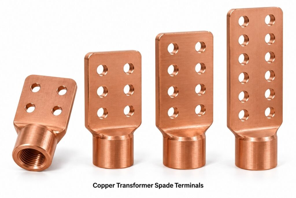
Cable Glands India manufactures copper transformer spade terminals and copper transformer spade connectors for electrical transformer bushing connections. These components convert a threaded bushing interface into a flat drilled terminal pad for bolted cable lugs, busbars and connection palms. Designs cover base-stem thread diameters from 3/8 inch to 2 inches in specified UNC, UNF or UNS forms, with 2 to 16 connection holes and natural or tin-plated surfaces. NEMA-pattern hole layouts are made to the approved interface drawing; electrical duty, clearances and mechanical loading are verified for the complete connection.
Product overview: threaded transformer spades
Copper transformer bushing spade terminals
A transformer spade is a substantial conductive component with a flat connection blade and a base that mates with the bushing conductor. The base may have a female threaded socket or a male threaded stem, depending on the equipment design. The drawing must identify this interface explicitly. A description such as “one-inch spade” does not establish pitch, thread gender, engagement depth or shoulder location. The pad accommodates bolted connections while the base transfers electrical current and mechanical loading into the bushing interface. The transition between blade and stem requires adequate section and a controlled radius, particularly when multiple cables impose bending forces.
NEMA-spaced terminal pads and drilled connection palms
NEMA-spaced transformer spades use an established bolting grid so compatible lug palms and busbar connections can be arranged predictably. A commonly specified power-terminal pattern uses 1.75-inch centres, equivalent to 44.45 mm, with 9/16-inch clearance holes for nominal half-inch hardware where the interface drawing requires this arrangement. Hole diameter, transverse spacing, edge distance and pad thickness must still be stated. Two-hole inline pads and larger two-column pads are different geometries. A request for sixteen holes does not establish a universal pad envelope or automatically allow sixteen cable lugs.
Threaded spade connectors for transformer bushings
The base thread can be manufactured across the requested 3/8-inch to 2-inch nominal diameter range. UNC identifies a coarse Unified thread series, UNF identifies a fine series, and UNS identifies a specified special Unified diameter-pitch combination. These terms are not interchangeable, and thread diameter alone is insufficient for ordering. Include threads per inch, internal or external form, tolerance class, handedness and useful thread length. For plated parts, define the finished thread acceptance condition. A thread that fits before plating may fail the mating gauge after coating if allowance and masking have not been planned.
Natural and tin-plated transformer terminals
Natural finish retains the underlying copper contact surface after cleaning, deburring and the agreed finishing operation. Tin plating produces a metallic contact coating that can help protect the interface from surface oxidation during storage and service. The coating is part of the joint specification, rather than a substitute for proper clamping pressure and surface preparation. Specify plating thickness, coating coverage, underplate if required, masking and adhesion criteria. Threads, flat contact faces and recessed sockets may have different coverage requirements. The procurement drawing should define them separately so final assembly does not depend on assumptions.
Two-hole through sixteen-hole spade configurations
Connection-hole counts from two to sixteen allow the terminal geometry to match the intended cable and busbar arrangement. Typical configurations include a two-hole inline blade and four-, six-, eight-, ten-, twelve-, fourteen- or sixteen-hole two-column pads. Odd-hole or single-column designs can also be reviewed against a drawing. Hole count is a geometric description, not a current rating. Lug width, bolt access, washer footprint, cable bend radius, interphase clearance and cable support determine how many practical terminations can occupy the pad. Large pads may require larger transition sections even when the original bushing thread remains unchanged.
Electrical OEM and utility drawing-based supply
Transformer manufacturers, repair facilities, utilities, distributors and EPC contractors can specify these parts through controlled drawings and purchasing descriptions. A complete enquiry identifies the bushing model or mating interface, material grade, blade envelope, hole pattern, thread designation and finish. Replacement projects should compare an existing part with the assembly drawing rather than relying on appearance alone. Changes in cable routing or conductor size can alter mechanical moments and local heating. Supply can therefore be organized around approved samples, dimensional reports and agreed production acceptance criteria, with changes reviewed before repeat manufacture.
Copper material selection for current-carrying spades
High-conductivity copper is appropriate when the electrical design requires low bulk resistance and effective heat conduction. C11000 electrolytic tough-pitch copper is a common starting point; oxygen-free grades can be considered when their specific processing or service characteristics are required. Copper remains mechanically sensitive to temper, forming history and temperature, so the designer must establish thread strength and joint loading. A highly conductive material does not eliminate interface resistance. Flatness, contact pressure and correct installation remain essential. Conductivity requirements should be expressed as a measured acceptance value where they are critical.
Key features
- Threaded bushing interfaces from 3/8 inch to 2 inches, to the specified diameter and pitch.
- UNC, UNF and drawing-defined UNS threads; internal or external base forms.
- Two to sixteen connection holes with drawing-controlled NEMA-pattern spacing.
- Natural copper or specified tin-plated finish.
- Forged and machined configurations with controlled pad-to-stem transitions.
- OEM drawing review for pad thickness, contact area, thread engagement and clearance.
- Inspection requirements defined before production; traceability documents by agreement.
Related terminal designs and engineering features
Forged copper transformer spades
A forged preform can place metal around the base and pad transition before final machining. Tooling, forging temperature and trimming operations depend on the selected alloy and part envelope. Forging does not by itself prove freedom from defects or guarantee electrical performance. The approved process must control laps, underfill, cracks and dimensional variation. Machining allowance should permit complete clean-up of the intended contact faces. The base-to-blade region deserves particular attention because it carries both current and cable-induced loading. Process selection is confirmed after drawing and volume review.
Tin-plated copper spade connectors
Tin-plated spade connectors require a defined coating specification and finished dimensions. Contact faces should be clean and suitable for plating before the coating is applied. Burrs, sharp edges and trapped machining residues can compromise coverage or later assembly. Thickness measurements should identify relevant locations and acceptance limits rather than quoting an unexplained average. Coating adhesion, appearance and any required underplate are agreed with the customer. Packaging should protect the finished face from abrasion. The electrical designer remains responsible for confirming that the complete plated joint meets the intended thermal and environmental requirements.
Copper terminal palms and transformer connection blades
Terminal palm and connection blade are useful descriptions of the flat bolting portion of the spade. Its net conductive section is reduced by drilled holes, especially near the base and at the narrowest ligament. A wider blade does not necessarily improve the limiting stem section. Designers should review current flow from the bushing into the pad and onward into each lug. Uneven loading can produce local temperature differences. Hole-position tolerances, surface flatness and parallelism should be related to the actual assembly, with sufficient tool access around the mounting hardware.
Threaded bushing adapters and stud-to-pad connectors
A stud-to-pad connector may screw onto an existing male bushing stud through an internal socket, while a male-stem terminal engages a female threaded interface. Both configurations should specify the electrical contact path, tightening method and locking arrangement. Do not assume that thread engagement alone defines the intended contact surface; some assemblies depend on a shoulder or other interface. The drawing should show bottoming clearance, engagement length and assembled orientation. Installation forces must not be transmitted through fragile bushing insulation. Use the bushing manufacturer’s approved assembly procedure and torque requirements.
Multi-hole transformer secondary terminals
Multi-hole spades are often associated with transformer secondary connections, where several conductors may need a common terminal surface. Their use is still governed by the transformer design and installation requirements. Parallel conductors should be arranged so their electrical paths, lengths and terminations support the intended current sharing. Cable weight and fault forces must be addressed through independent support. Bolted lug stacks require specific approval and cannot be assumed from the number of available holes. A properly selected terminal therefore forms one part of a coordinated bushing, lug, conductor and support assembly.
Custom NEMA-pad transformer connector assemblies
Custom spades may incorporate alternate offsets, longer necks, different pad widths, selected hole omissions or special threaded bases. These changes can solve clearance problems but also change lever arm, heat dissipation and fault-force response. Submit the surrounding assembly envelope where possible, including phase spacing and insulating barriers. A custom hole pattern should be labelled accurately rather than described as universally NEMA compliant. Drawing-controlled production permits individual interface dimensions to be inspected and reported. Prototype assembly checks are useful before committing to a production batch or distributor replacement programme.
Technical specifications
| Parameter | Specification / selection basis |
|---|---|
| Brand | Cable Glands India |
| Product category | Forging and Hot Stamping; electrical transformer terminals |
| Base material | C11000 ETP copper; C10100/C10200 oxygen-free copper or other approved copper grade |
| Base thread diameter | 3/8 inch to 2 inches nominal |
| Thread forms | UNC, UNF or explicitly specified UNS; internal or external to drawing |
| Thread acceptance | Diameter, pitch, class, engagement and after-plating condition to drawing |
| Connection holes | 2–16 holes; inline, two-column or approved custom pattern |
| Common NEMA-pattern pitch | 1.75 inches / 44.45 mm where specified; confirm both axes |
| Common clearance hole | 9/16 inch / 14.29 mm for specified 1/2-inch bolting; confirm drawing |
| Surface finish | Natural or tin plated; thickness and coverage by agreement |
| Dimensions and tolerances | Approved customer drawing; no universal pad size implied |
| Current and voltage rating | Established for the complete transformer connection; no rating inferred from hole count |
| Production route | Forging/hot stamping and machining, or an approved alternative |
| Commercial rate | US$ 19.00/kg indicative; subject to confirmed quotation |
Raw materials and international grade comparison
The following table identifies material families and commonly compared specifications. Cross-references are procurement aids, not permission to substitute. Chemical limits, product form, temper, conductivity and mechanical requirements must be checked against the current purchase specification. Standards may cover feedstock or a manufacturing process without certifying the finished transformer connection.
| Material / UNS | EN or other commonly compared designation | Selection note |
|---|---|---|
| C11000 ETP copper | Cu-ETP / CW004A; JIS C1100 family | Common high-conductivity choice; verify chemistry and product-form specification |
| C10100 oxygen-free electronic copper | Cu-OFE / CW009A | High-purity oxygen-free option; application approval required |
| C10200 oxygen-free copper | Cu-OF / CW008A | Oxygen-free family; confirm grade-specific acceptance |
| C14500 tellurium copper | CuTeP / CW118C, commonly compared | Machinability-focused copper alloy; conductivity and strength differ from ETP |
C11000 ETP copper is specified for high conductivity and contains controlled oxygen. Oxygen-free copper is selected for particular processing or service needs rather than because all applications require it. Tellurium copper improves machining behaviour but is a different alloy with its own property limits. Temper and subsequent forming affect strength and ductility, particularly around threads and the pad neck. A material certificate should identify the exact grade and product standard instead of simply stating “pure copper”.
Thread and hole combination selection table
The matrix below describes enquiry combinations available for engineering review, rather than a stock list or approved ampacity schedule. Each row can be paired with the shown hole counts only after the stem, neck, pad and bushing loads have been checked. UNC and UNF entries are example standard designations; UNS pitch must be specified separately. Holes above eight generally use an extended drawing-controlled pad.
| Nominal base diameter | UNC example | UNF example | Hole-count options for review | UNS option |
|---|---|---|---|---|
| 3/8″ | 3/8-16 UNC | 3/8-24 UNF | 2, 4, 6, 8, 10, 12, 14, 16 | Pitch to drawing |
| 1/2″ | 1/2-13 UNC | 1/2-20 UNF | 2, 4, 6, 8, 10, 12, 14, 16 | Pitch to drawing |
| 5/8″ | 5/8-11 UNC | 5/8-18 UNF | 2, 4, 6, 8, 10, 12, 14, 16 | Pitch to drawing |
| 3/4″ | 3/4-10 UNC | 3/4-16 UNF | 2, 4, 6, 8, 10, 12, 14, 16 | Pitch to drawing |
| 7/8″ | 7/8-9 UNC | 7/8-14 UNF | 2, 4, 6, 8, 10, 12, 14, 16 | Pitch to drawing |
| 1″ | 1-8 UNC | 1-12 UNF | 2, 4, 6, 8, 10, 12, 14, 16 | Pitch to drawing |
| 1-1/8″ | 1-1/8-7 UNC | 1-1/8-12 UNF | 2, 4, 6, 8, 10, 12, 14, 16 | Pitch to drawing |
| 1-1/4″ | 1-1/4-7 UNC | 1-1/4-12 UNF | 2, 4, 6, 8, 10, 12, 14, 16 | Pitch to drawing |
| 1-1/2″ | 1-1/2-6 UNC | 1-1/2-12 UNF | 2, 4, 6, 8, 10, 12, 14, 16 | Pitch to drawing |
| 1-3/4″ | 1-3/4-5 UNC | Specify pitch; do not assume UNF | 2, 4, 6, 8, 10, 12, 14, 16 | Pitch to drawing |
| 2″ | 2-4.5 UNC | Specify pitch; do not assume UNF | 2, 4, 6, 8, 10, 12, 14, 16 | Pitch to drawing |
| Hole count | Illustrative layout | Drawing requirement |
|---|---|---|
| 2 | 1 column × 2 rows | Inline pitch, pad width and edge distance |
| 4 | 2 columns × 2 rows | Both-axis pitch and contact envelope |
| 6 | 2 columns × 3 rows | Pad length, thickness and stem transition |
| 8 | 2 columns × 4 rows | Cable access and bending load |
| 10 | 2 columns × 5 rows | Extended pad and support review |
| 12 | 2 columns × 6 rows | Thermal and mechanical review |
| 14 | 2 columns × 7 rows | Full assembly envelope approval |
| 16 | 2 columns × 8 rows | Net section, connection layout and bushing load approval |
Product types and variants
| Variant | Configuration | Important ordering detail |
|---|---|---|
| Natural copper spade | Unplated cleaned contact surfaces | Storage protection and installation preparation |
| Tin-plated copper spade | Coated pad and selected base surfaces | Thickness, coverage, underplate and masking |
| Female-base terminal | Threaded socket over a bushing stud | Useful depth and bottoming clearance |
| Male-stem terminal | External thread into mating interface | Stem length, shoulder and thread runout |
| Compact two-hole terminal | Narrow inline blade | Lug footprint and bolt access |
| Multi-hole transformer spade | Four to sixteen holes | Pad envelope and cable support |
| Special-pitch connector | Drawing-defined UNS base thread | Exact diameter, TPI and tolerance class |
Industrial applications
Distribution transformers and secondary cable connections
Distribution-transformer assemblies can use threaded spades to connect bushing conductors to cable lugs or bus links. Selection depends on transformer rating, operating temperature, enclosure space and the approved bushing interface. Outdoor equipment also requires attention to contamination, moisture and corrosion protection. The terminal should be coordinated with the specified conductor metal and lug system. Tin plating alone does not establish an aluminium-compatible joint. Any dissimilar-metal connection requires an approved connector arrangement, surface preparation and installation instructions. Maintain the designed insulation distances around the completed assembly.
Power-transformer auxiliaries, retrofits and OEM programmes
Custom spades can be reviewed for industrial transformer assemblies, approved replacement programmes and suitable auxiliary connections. EPC contractors and utility maintenance teams should identify the existing equipment configuration before selecting a replacement. An OEM drawing provides a stronger basis than photographs because concealed socket dimensions and contact shoulders may determine compatibility. Distributor catalogues should list material, finish and complete thread designation alongside hole count. For repeat programmes, a controlled part number and revision prevent mixed supply. Any duty change should trigger review of the complete connection.
Manufacturing process and production controls
| Stage | Process explanation | Control point |
|---|---|---|
| Drawing review | Check mating interface, material, pad geometry, finish and inspection requirements | Resolve missing pitch, class and engagement information |
| Material receipt | Identify approved rod, bar or forging stock | Certificate and batch identification |
| Blank preparation | Cut suitable stock for the selected forming route | Blank mass and cleanliness |
| Forging / hot stamping | Form the approved preform where appropriate | Temperature, fill, laps and transition geometry |
| Trimming and conditioning | Remove flash and prepare machining references | Avoid damage to functional surfaces |
| CNC machining | Finish base, shoulder, socket or external stem | Concentricity and engagement geometry |
| Pad drilling and facing | Machine hole pattern and contact surfaces | Position, flatness and residual burrs |
| Threading and gauging | Produce and inspect specified Unified thread | Finished class and useful thread length |
| Cleaning / plating | Apply natural finish or specified tin coating | Coverage, adhesion and finished fit |
| Final inspection and packing | Verify drawing requirements and protect contact faces | Identification and agreed inspection records |
Manufacturing planning should preserve a consistent datum relationship between the base and blade. If the hole pattern is machined independently from the threaded base without controlled location, assembly orientation may vary. Where necessary, the drawing should define angular alignment or a method of final positioning. Deburring must remove cutting edges without rounding away functional contact area or changing hole size. Cleanliness is especially important in blind threaded sockets, where swarf can prevent full engagement. Finished components are handled and packed to reduce dents, plating abrasion and contamination before installation.
Quality standards, inspection and certification
Applicable references are selected by product form and customer contract. ASTM B124/B124M addresses copper and copper-alloy forging rod, bar and shapes; ASTM B283/B283M addresses specified copper and copper-alloy die forgings. ASME B1.1 is relevant to Unified inch screw threads. ASTM B545 can be specified for electrodeposited tin coatings. NEMA-pattern terminology describes an interface arrangement and is not a third-party product certification. UL listing, IEEE testing, IEC compliance or utility approval must be supported by the actual product-specific evidence; none is implied simply by the material or hole spacing.
| Characteristic | Suggested verification | Acceptance basis |
|---|---|---|
| Alloy identity | Material certificate and agreed chemistry verification | Specified grade and batch |
| Critical dimensions | Calibrated dimensional inspection | Approved drawing revision |
| Threads | Suitable GO/NO-GO gauges and depth checks | Specified size, pitch, class and coating condition |
| Pad pattern | Hole diameter and positional measurement | Specified pitch and edge distances |
| Contact surfaces | Flatness and visual inspection | Agreed drawing criteria |
| Tin coating | Thickness and adhesion checks where ordered | Coating specification and sampling plan |
| Electrical performance | Resistance and temperature-rise tests where contracted | Complete connection and agreed test method |
| Mechanical performance | Torque, pull or bending verification where required | Approved assembly and application loads |
Management-system certificates and environmental declarations should be requested for the supplying entity and relevant scope. A management-system certificate does not establish a terminal current rating. For qualification programmes, agree first-article dimensions, material documentation, sample quantity and test responsibilities before manufacture. The drawing should identify critical characteristics and any special sampling requirements. If a customer requires independent testing or a particular laboratory, include that requirement in the enquiry so cost and lead time can be assessed. Production approval should refer to the same material, finish and geometry that will be supplied.
Installation and connection-design guidance
Use the transformer and bushing manufacturer’s approved installation procedure. Confirm thread compatibility before assembly and avoid forcing a terminal onto a damaged or mismatched stud. Protect the bushing from bending and torsion while tightening. Contact faces should be prepared according to the selected lug and coating system. Bolt grade, washers, joint compound where applicable and tightening torque belong to the complete joint specification. Do not derive torque solely from nominal thread size because copper strength, engagement depth, lubrication and the bushing construction affect the permissible value.
Current capacity must be validated with the actual conductor arrangement, ambient conditions, enclosure ventilation and permissible temperature rise. Multiple holes do not guarantee equal current distribution or a higher continuous rating. At fault conditions, electromagnetic forces can act through long cable runs and extended pads, so independent cable support is important. Maintain clearances after cables are installed, not only when the bare terminal is inspected. For maintenance, follow the equipment owner’s approved isolation, inspection and retightening policy. Discoloured joints, damaged coating or loose hardware require assessment of the underlying cause.
Why choose Cable Glands India
Cable Glands India offers drawing-based coordination of copper material, forming, machining and finishing requirements for industrial metal components. The purchasing discussion can therefore address the entire terminal specification: mating thread, pad geometry, connection pattern and final surface condition. This is useful for OEMs managing repeat part numbers, distributors building technically clear catalogues and EPC teams coordinating replacement interfaces. Enquiries are reviewed against the requested manufacturing route and acceptance requirements. Confirmed quotations identify scope, documentation and any tooling or qualification work rather than relying on a generic component description.
Frequently asked questions
What is a copper transformer spade terminal?
It is a conductive threaded-base component with a flat drilled pad used to connect a transformer bushing interface to bolted lugs or busbars. The base, pad and installed joint must be selected for the equipment design.
Are these the same as small push-on spade terminals?
No. These are substantial transformer connection pads with bolted holes and a threaded bushing interface. Small quick-disconnect blade terminals are a different product family with different dimensions and use.
What does NEMA spacing mean here?
It describes the specified bolting pattern. A common arrangement uses 1.75-inch centres and 9/16-inch holes for the specified half-inch bolting. Confirm the exact pattern, pad dimensions and applicable interface requirements on the drawing.
Can I order two to sixteen holes?
Yes, configurations in that range can be reviewed. Pad size, stem size, cable loading and electrical duty must be checked together. The combination table is an enquiry matrix rather than evidence that every combination is already qualified.
Which thread details are required?
Provide diameter, threads per inch, UNC/UNF/UNS designation, internal or external form, class, handedness and useful engagement length. UNS always requires an explicit pitch. State whether the thread is gauged after plating.
Can the spades be tin plated?
Yes. Define coating thickness, coverage, adhesion requirements and any underplate or masking. Final thread fit and contact-face condition must be included in the acceptance plan. Tin plating does not replace correct joint design.
Can brass and copper terminals be interchanged?
Only after engineering approval. Their conductivity, strength, thermal behaviour and corrosion characteristics differ. Matching holes and threads do not prove equivalent temperature-rise or mechanical performance in the installed transformer connection.
Is a current rating determined by the hole count?
No. Current rating depends on material, conductive section, contact resistance, conductor arrangement and thermal conditions. Verify the complete assembly using the equipment requirements and agreed testing rather than assigning amperes from hole count.
Are international material grades exact equivalents?
Not automatically. The comparison table identifies commonly related families. Chemistry limits, temper, product form and required properties must be compared before substitution. The purchase order should identify the approved grade and standard.
What information should accompany a quotation request?
Send the drawing revision, alloy, thread designation, hole pattern, pad dimensions, finish, quantities and required documents. Include the mating bushing details and application duty when available, together with packing and delivery requirements.
Equivalent search terms in export markets
| Language | Related product terms |
|---|---|
| Spanish | terminales de pala de cobre para transformadores; conectores de pala de cobre; terminales roscados NEMA |
| Russian | медные выводы-лопатки трансформатора; медные контактные пластины; резьбовые выводы NEMA |
| French | bornes à plage en cuivre pour transformateurs; connecteurs à plage en cuivre; bornes filetées NEMA |
| Portuguese | terminais tipo pá de cobre para transformadores; conectores tipo pá de cobre; terminais roscados NEMA |
| Italian | terminali a paletta in rame per trasformatori; connettori a paletta in rame; terminali filettati NEMA |
Related products and linked engineering terms
- Forging and Hot Stamping
- Brass Transformer Spade Terminals and Brass Transformer Spade Connectors
- Brass Forged Parts and Forged Components
- Brass CNC Machined Parts from Hot Forging
- Copper Forging and Copper Forged Parts
- Copper Ground Ferrules by Impact Extrusion and Cold Forging
- Bronze Transformer Spades and Spade Connectors
- Copper Cable Lugs
- Transformer Tank Grounding Connectors
Request a drawing-based quotation
Send Cable Glands India your copper transformer spade terminal drawing and required quantity. Identify the full base thread, two-to-sixteen-hole layout, natural or tin-plated finish and electrical application. Include inspection, qualification and delivery requirements so the quotation covers the required supply scope. Indicative rate: US$ 19.00/kg. Contact our team through the enquiry page to confirm the final specification and commercial offer.